For the purposes of this lab, OpenXC has provided the circuit board and components to make your own Retro Gauge. If you wish to modify your gauge or a friend wants to build their own, visit the GitHub repository to download the PCB schematics and use your favorite low-volume fab house to manufacture the gauge (see the resources at the bottom of the page for some suggestions).
The complete list of components required to build a Retro Gauge can also be found on GitHub in the BOM.
Once you have your PCB and all of your materials, follow this Instructable on soldering all of the components the PCB.
When you're done soldering, it's a good idea to check all of the connections with a multimeter.
Now that your circuit board is assembled, it is time to flash the firmware onto the Arduino. This requires an FTDI cable or adapter - follow this tutorial on flashing to get started.
Once you have the right cables attached, see the docs on compiling and flashing the Retro Gauge firmware.
After flashing the firmware, the gauge runs a self-test procedure that will show all possible digits on the display, show all colors on the LEDs and spin the motor a bit. This self-test happens every time it powers on and just takes a couple of seconds.
If you've checked all of your electrical connections, but the self-test still isn't perfect, here are some things to check:
Making your housing is as simple as downloading the .stl files from GitHub and printing at your local TechShop or hackerspace. If you do not have access to either one of these facilities, you can print the housing using a 3D fabrication house listed above.
Equipment and Material Needed
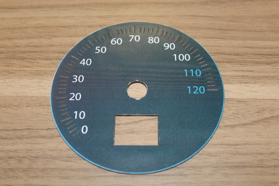
Download and print out the Gauge Face PDF file. Cut along the outline of the gauge and cut out the shaded area. If you want to make any modifications to the gauge face, you can download the gaugeFace.ai file and use it as a template.
Equipment and Material Needed
When we designed the gauge, we wanted to use tools that were commonly available in hobbyist spaces but also available to a tinkerer in his or her garage.
With this in mind, it is important to note that a gauge face can be made multiple ways. However, with the tools available at TechShop, we believe this is the easiest way to make one. The Lasercam makes cutting a breeze; however, it is not necessary, and the pattern could simply be cut by hand using a hobby knife.
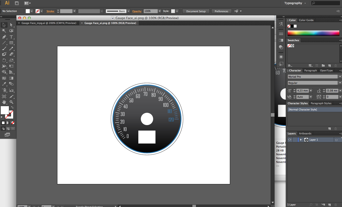
Using a photo editor like Photoshop or CorelDraw, design your gauge face. Make sure to download the GaugeFace.dxf from GitHub for the parameters of your design.
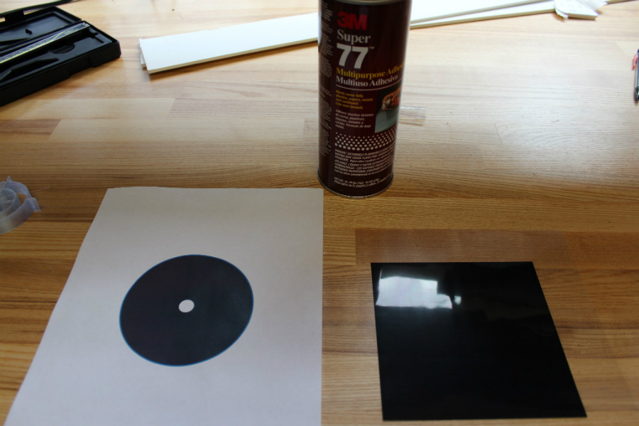
Print out the design on the weighted paper and also print a back square on the transparent. This will block the light from shining through the face in places that you do not want. Using the multipurpose adhesive, spray the back of the weighted paper and stick the black square over the gauge face. Do not worry about alignment, the lasercam will cut out the gauge face.
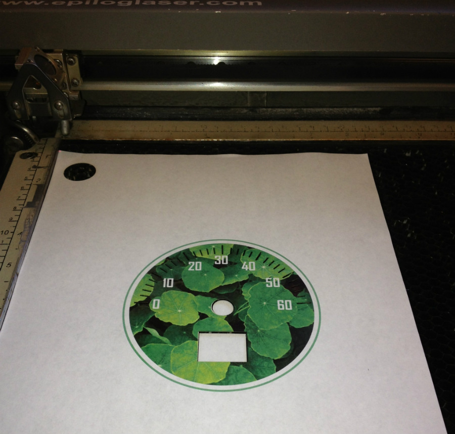
Align the paper on the lasercam and using gaugeFace.dxf, cut out the gauge face. You can add elements to the .dxf file if you wish to cut out numbers or 'tick' marks to allow light to shine through.
Tip: Create a rectangle on your design to use as a reference for setting up the paper on the lasercam. Using the laser pointer on the lasercam, you can reference your physical printed design with .dxf file for increased accuracy.
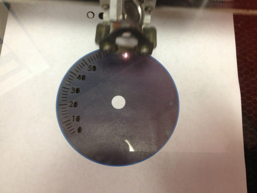
Using the same DXF file, cut out the acrylic to create the backing for the gauge face.
Using the multipurpose adhesive, attach the gauge face design the to acrylic and voilà, you have your very own Retro Gauge face!
Finally, time to put all of the pieces together!
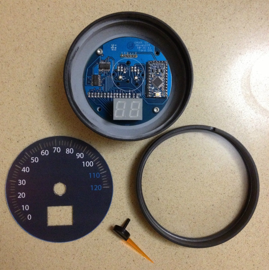
Place the PCB in the housing and screw it together.
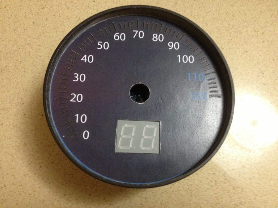
Then place the gauge face on top of the PCB
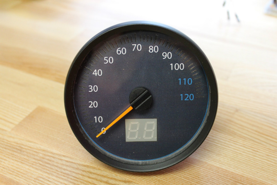
Your very first OpenXC Retro Gauge!
Resources